Analog Pin Overview
The Arduino Uno features 6 analog input pins labeled A0 through A5. These pins are essential for reading analog sensors and converting real-world analog signals into digital values that your Arduino can process.
How Analog Input Works
Voltage Range
Arduino analog pins can read voltages between 0V and 5V. The voltage is converted to a digital value using the built-in Analog-to-Digital Converter (ADC).
Analog-to-Digital Conversion (ADC)
The Arduino Uno uses a 10-bit ADC, which means it converts the analog voltage into a digital value ranging from 0 to 1023.
| Input Voltage | Digital Value | Description |
|---|---|---|
| 0 V | 0 | Minimum value (GND) |
| 2.5 V | 512 | Approximately middle value |
| 5 V | 1023 | Maximum value (VCC) |
Resolution Formula
Each step represents approximately 4.88 mV (0.00488V)
Pin Location on Arduino Uno
Analog pins are located on the bottom right side of the Arduino Uno
Reading Analog Values
Basic Syntax
int analogRead(int pin);The analogRead() function reads the voltage on an analog pin and returns a value between 0 and 1023.
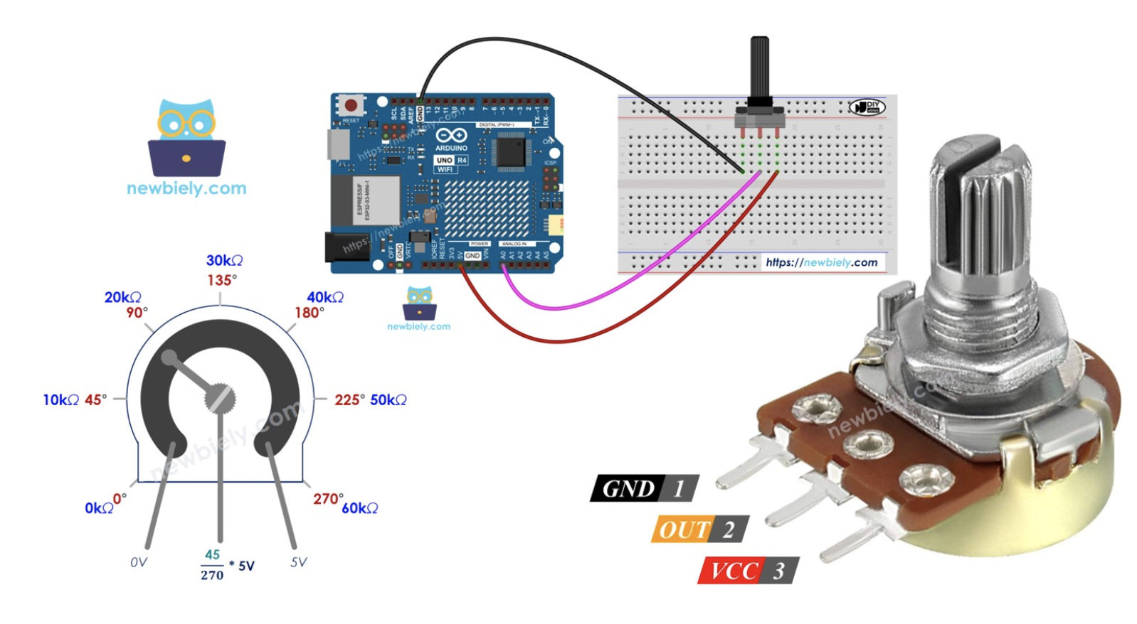
Example 1: Simple Analog Read
// Read potentiometer connected to A0
int potPin = A0;    // Analog pin A0
int potValue = 0;  // Variable to store the value

void setup() {
  Serial.begin(9600);  // Initialize serial communication
}

void loop() {
  potValue = analogRead(potPin);  // Read analog value

  Serial.print("Potentiometer Value: ");
  Serial.println(potValue);  // Print value (0-1023)

  delay(500);  // Wait 500ms
}
Wiring: Connect the potentiometer's middle pin to A0, one outer pin to 5V, and the other to GND.
Converting Analog Values
Converting to Voltage
int sensorPin = A0;
int sensorValue = 0;
float voltage = 0.0;

void setup() {
  Serial.begin(9600);
}

void loop() {
  sensorValue = analogRead(sensorPin);

  // Convert to voltage (0-5V)
  voltage = sensorValue * (5.0 / 1024.0);

  Serial.print("Sensor Value: ");
  Serial.print(sensorValue);
  Serial.print(" | Voltage: ");
  Serial.print(voltage);
  Serial.println(" V");

  delay(1000);
}
Using map() Function
The map() function is useful for converting the 0-1023 range to other ranges.
int potPin = A0;      // Potentiometer on A0
int ledPin = 9;       // LED on PWM pin 9
int potValue = 0;
int brightness = 0;

void setup() {
  pinMode(ledPin, OUTPUT);
  Serial.begin(9600);
}

void loop() {
  potValue = analogRead(potPin);

  // Map 0-1023 to 0-255 for PWM
  brightness = map(potValue, 0, 1023, 0, 255);

  analogWrite(ledPin, brightness);

  Serial.print("Pot: ");
  Serial.print(potValue);
  Serial.print(" | Brightness: ");
  Serial.println(brightness);

  delay(100);
}
Wiring Instructions:
- Potentiometer: Pin 1 (left) to GND, Pin 2 (middle) to A0, Pin 3 (right) to 5V
- LED Circuit: Arduino Pin 9 → 220Ω Resistor → LED Anode (+)
- LED Cathode (-): Connect to Arduino GND
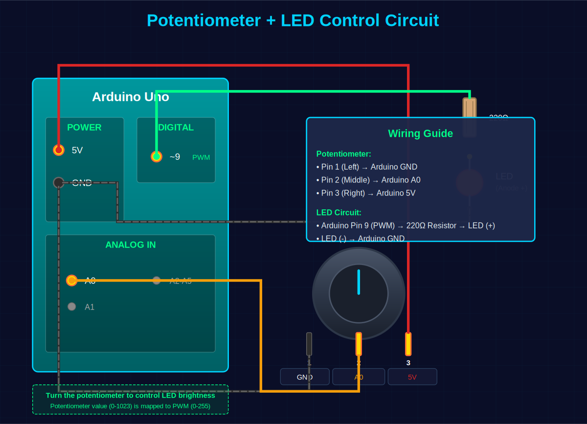
map() function converts this to 0-255 (PWM range), and analogWrite() adjusts the LED brightness. Turn the potentiometer knob to see the LED brightness change in real-time!
Reading Multiple Analog Pins
void setup() {
  Serial.begin(9600);
  Serial.println("Reading all analog pins...");
}

void loop() {
  // Read all 6 analog pins
  for (int pin = 0; pin < 6; pin++) {
    int value = analogRead(pin);

    Serial.print("A");
    Serial.print(pin);
    Serial.print(": ");
    Serial.print(value);
    Serial.print(" | ");
  }
  Serial.println();

  delay(1000);
}
Common Sensors Using Analog Pins
int tempPin = A0;

void setup() {
  Serial.begin(9600);
}

void loop() {
  int reading = analogRead(tempPin);

  // Convert to voltage
  float voltage = reading * 5.0 / 1024.0;

  // Convert to temperature (Celsius)
  // TMP36: 10mV per degree with 500mV offset
  float temperatureC = (voltage - 0.5) * 100.0;

  Serial.print("Temperature: ");
  Serial.print(temperatureC);
  Serial.println(" °C");

  delay(1000);
}
Wiring: TMP36 pin 1 (left) to 5V, pin 2 (middle) to A0, pin 3 (right) to GND.
int ldrPin = A0;
int ledPin = 13;

void setup() {
  pinMode(ledPin, OUTPUT);
  Serial.begin(9600);
}

void loop() {
  int lightLevel = analogRead(ldrPin);

  Serial.print("Light Level: ");
  Serial.println(lightLevel);

  // Turn on LED when dark (low reading)
  if (lightLevel < 500) {
    digitalWrite(ledPin, HIGH);
    Serial.println("LED ON - It's dark!");
  } else {
    digitalWrite(ledPin, LOW);
    Serial.println("LED OFF - It's bright!");
  }

  delay(500);
}
Wiring: LDR and 10kΩ resistor in series between 5V and GND. Connect A0 to the junction between LDR and resistor.
int moisturePin = A1;
int pumpPin = 8;

void setup() {
  pinMode(pumpPin, OUTPUT);
  Serial.begin(9600);
}

void loop() {
  int moisture = analogRead(moisturePin);

  // Convert to percentage (calibrate these values)
  int moisturePercent = map(moisture, 1023, 0, 0, 100);

  Serial.print("Moisture: ");
  Serial.print(moisturePercent);
  Serial.println("%");

  // Activate water pump if soil is too dry
  if (moisturePercent < 30) {
    digitalWrite(pumpPin, HIGH);
    Serial.println("Watering...");
  } else {
    digitalWrite(pumpPin, LOW);
  }

  delay(2000);
}
Technical Specifications
| Parameter | Value | Notes |
|---|---|---|
| Number of Pins | 6 (A0-A5) | On Arduino Uno |
| Voltage Range | 0V - 5V | Do not exceed 5V |
| ADC Resolution | 10-bit | 1024 possible values |
| Output Range | 0 - 1023 | Integer values |
| Voltage per Step | ~4.88 mV | 5V ÷ 1024 |
| Reading Time | ~100 μs | Approximately |
| Input Impedance | 100 MΩ | High impedance |
| Alternative Use | Digital I/O | Can use as pins 14-19 |
Best Practices & Tips
✓ Do's
- Always stay within 0-5V range
- Use appropriate pull-down or pull-up resistors when needed
- Add a small delay after reading multiple pins consecutively
- Calibrate sensors for accurate readings
- Use averaging for stable readings from noisy sensors
- Check sensor datasheets for voltage output specifications
✗ Don'ts
- Never exceed 5V on analog pins - this can damage the Arduino
- Don't connect sensors without checking voltage levels first
- Avoid reading too frequently - give ADC time to settle (>100μs)
- Don't assume exact voltage measurements - ±2% error is normal
- Don't use long wires without considering noise interference
Noise Reduction Technique
int readAnalogAverage(int pin, int samples) {
  long sum = 0;

  for (int i = 0; i < samples; i++) {
    sum += analogRead(pin);
    delay(10);
  }

  return sum / samples;
}

void setup() {
  Serial.begin(9600);
}

void loop() {
  int avgValue = readAnalogAverage(A0, 10);

  Serial.print("Averaged Value: ");
  Serial.println(avgValue);

  delay(1000);
}
Summary
Arduino analog pins A0-A5 are powerful tools for interfacing with the real world. Key points to remember:
- 6 analog input pins (A0-A5) on Arduino Uno
- Read voltages from 0V to 5V
- 10-bit resolution provides values from 0 to 1023
- Use
analogRead(pin)to read values - Can also function as digital pins 14-19
- Perfect for sensors: temperature, light, moisture, potentiometers, and more
- Always protect pins from over-voltage conditions
Practice Exercise
Objective: Create a system that reads three different sensors simultaneously and displays formatted data.
Requirements:
- Connect a potentiometer to A0
- Connect an LDR circuit to A1
- Connect a temperature sensor to A2
- Read all three sensors every second
- Display formatted output with labels
- Add conditions to trigger warnings (e.g., too hot, too dark)
// Your code here!
// Hint: Use arrays to store pin numbers and sensor names
// Hint: Create functions for each sensor type
// Hint: Format output nicely with Serial.print()