What is Arduino?
Open-source electronics platform based on easy-to-use hardware and software, designed for creating interactive electronic projects.
✨ Key Features
- Easy to use for beginners
- Powerful for professionals
- Large community support
- Affordable and accessible
- Cross-platform IDE
🚀 Applications
- Robotics projects
- Home automation
- IoT devices
- Sensor systems
- Interactive art installations
Arduino UNO - Technical Specifications
| Component | Specification |
|---|---|
| Microcontroller | ATmega328P |
| Operating Voltage | 5V |
| Input Voltage | 7-12V (recommended) |
| Digital I/O Pins | 14 (6 with PWM capability) |
| Analog Input Pins | 6 (A0-A5) |
| Flash Memory | 32 KB |
| SRAM | 2 KB |
| Clock Speed | 16 MHz |
🔌 Key Components
- USB Port: Programming & power supply
- Power Jack: External power (7-12V)
- Digital Pins: 0-13 for I/O operations
- Analog Pins: A0-A5 for sensor reading
- Power Pins: 5V, 3.3V, GND, VIN
- Reset Button: Restart program
- Built-in LED: Connected to pin 13
⚡ PWM Pins
Pins with PWM capability (marked with ~):
- Pin 3
- Pin 5
- Pin 6
- Pin 9
- Pin 10
- Pin 11
These pins can produce analog-like output using Pulse Width Modulation
Understanding the Breadboard
A solderless prototyping board that allows you to build and test circuits without permanent connections.
🔧 Structure
- Power Rails (Vertical): Red (+) and Blue (-) lines running along both sides
- Terminal Strips (Horizontal): 5 holes connected internally in each row
- Center Gap: Separates two sides, perfect for IC chips
✅ Advantages
- No soldering required
- Reusable for multiple projects
- Easy to modify circuits
- Quick prototyping
- Beginner-friendly
- Cost-effective
Circuit 1: Basic LED Blink
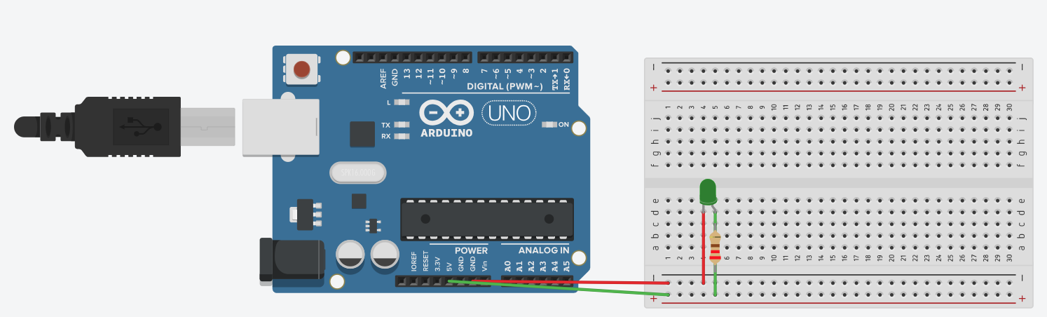
📦 Components Needed
- Arduino UNO board
- Breadboard
- LED (Green) - 1 unit
- 220Ω Resistor (Red-Red-Brown)
- Jumper wires (3 pieces)
- USB cable for programming
🔌 Step-by-Step Connections
- Step 1: Connect Arduino GND to breadboard ground rail (blue)
- Step 2: Connect LED cathode (-) short leg to ground rail
- Step 3: Connect LED anode (+) long leg to resistor
- Step 4: Connect resistor other end to breadboard row
- Step 5: Connect Arduino Pin 6 to same breadboard row
⚡ Important: LED Polarity
Long leg = Anode (+) → Connects to resistor
Short leg = Cathode (-) → Connects to ground
If connected backwards, the LED won't light up!
Code: Basic LED Blink
📋 Code Structure
setup(): Runs once when Arduino starts. Initialize pins, serial communication, and variables.
loop(): Runs continuously after setup. Contains main program logic.
🔑 Key Functions Used
pinMode(pin, OUTPUT)- Configure pindigitalWrite(pin, HIGH/LOW)- Turn on/offdelay(ms)- Pause executionSerial.begin(9600)- Start serialSerial.println()- Print to monitor
Circuit 2: Push Button LED Control

📦 Additional Components
- All components from Circuit 1
- Push button switch (1 unit)
- Additional jumper wires (2 pieces)
💡 Note: No external resistor needed for button - we use Arduino's internal pull-up resistor!
🔌 New Connections
- Button Pin 1: Connect to Arduino Pin 13
- Button Pin 2: Connect to Ground rail
- LED Circuit: Remains the same as Circuit 1
⚙️ How it works:
• Button pressed = LOW signal
• Button released = HIGH signal (pull-up)
🎯 Objective
LED turns ON when button is pressed, OFF when released - creating an interactive circuit controlled by user input!
Code: Push Button LED Control
🔑 Key Concept: INPUT_PULLUP
The INPUT_PULLUP mode enables an internal resistor (20-50kΩ) that pulls the pin to HIGH (5V) when the button is not pressed.
When you press the button, it connects the pin to ground (GND), making it read LOW.
• Button NOT pressed → Pin reads HIGH
• Button pressed → Pin reads LOW
• This inverted logic is why we check
if (buttonState == LOW)
PWM - LED Fading Effect
Pulse Width Modulation (PWM) allows us to simulate analog output on digital pins by rapidly switching between HIGH and LOW.
📊 PWM Value Range
0 = Completely OFF (0% duty cycle)
64 = 25% brightness
128 = 50% brightness
192 = 75% brightness
255 = Full brightness (100% duty cycle)
~ PWM-Capable Pins
Only these pins can use analogWrite():
- Pin 3
- Pin 5
- Pin 6 ← (We're using this)
- Pin 9
- Pin 10
- Pin 11
Look for the ~ symbol next to the pin number on the board!
Essential Arduino Functions Reference
📤 Output Functions
pinMode(pin, OUTPUT)
Configure pin as output
digitalWrite(pin, HIGH/LOW)
Set digital pin to 5V (HIGH) or 0V (LOW)
analogWrite(pin, 0-255)
PWM output with duty cycle 0-255
📥 Input Functions
pinMode(pin, INPUT_PULLUP)
Configure pin as input with internal pull-up
digitalRead(pin)
Read digital value: HIGH or LOW
analogRead(pin)
Read analog value: 0-1023 (10-bit ADC)
⏱️ Timing Functions
delay(milliseconds)
Pause program for specified time
millis()
Returns time (ms) since program started
delayMicroseconds(us)
Microsecond-precision delays
💬 Serial Communication
Serial.begin(9600)
Initialize serial at 9600 baud rate
Serial.println(data)
Print data with newline
Serial.print(data)
Print data without newline
Best Practices & Troubleshooting
🔧 Hardware Best Practices
- Always check LED polarity before connecting
- Use appropriate resistor values (220Ω-1kΩ for LEDs)
- Verify all connections before powering on
- Use color-coded wires for organization
- Disconnect power when modifying circuits
- Keep breadboard neat and organized
💻 Software Best Practices
- Comment your code clearly
- Use meaningful variable names
- Initialize all variables properly
- Use Serial Monitor for debugging
- Test code incrementally
- Save versions of working code
⚠️ Safety Guidelines
- Never exceed voltage ratings (max 5V on pins)
- Avoid short circuits (connecting + to - directly)
- Always use current-limiting resistors with LEDs
- Don't connect high voltage to Arduino pins
- Check component datasheets for specifications
- Keep liquids away from electronics
🐛 Common Problems & Solutions
LED Not Working?
- Check LED polarity (long leg = +)
- Verify resistor is connected
- Confirm correct pin number in code
- Try different LED (may be burnt)
Button Not Responding?
- Check button orientation on breadboard
- Verify INPUT_PULLUP is used
- Add debouncing delay (50ms)
- Test with Serial.println(buttonState)
🎯 Practice Challenges
Challenge 1: Traffic Light System
Build a 3-LED traffic light (Red, Yellow, Green) that cycles through proper sequences: Red (5s) → Yellow (2s) → Green (5s) → Yellow (2s)
Challenge 2: Multi-Level Brightness
Use a button to cycle through 4 brightness levels: OFF → DIM (64) → MEDIUM (128) → BRIGHT (255)
Challenge 3: Reaction Timer Game
LED lights up after random delay. Measure how fast user presses button using millis()